MWA technology has been developed to withstand the challenges of the Murchison outback, including extreme temperatures, lightning storms, highly acidic soil, and very curious fauna. Learn more about the interconnected parts of our signal chain through the animated video and information sections below.
Antenna
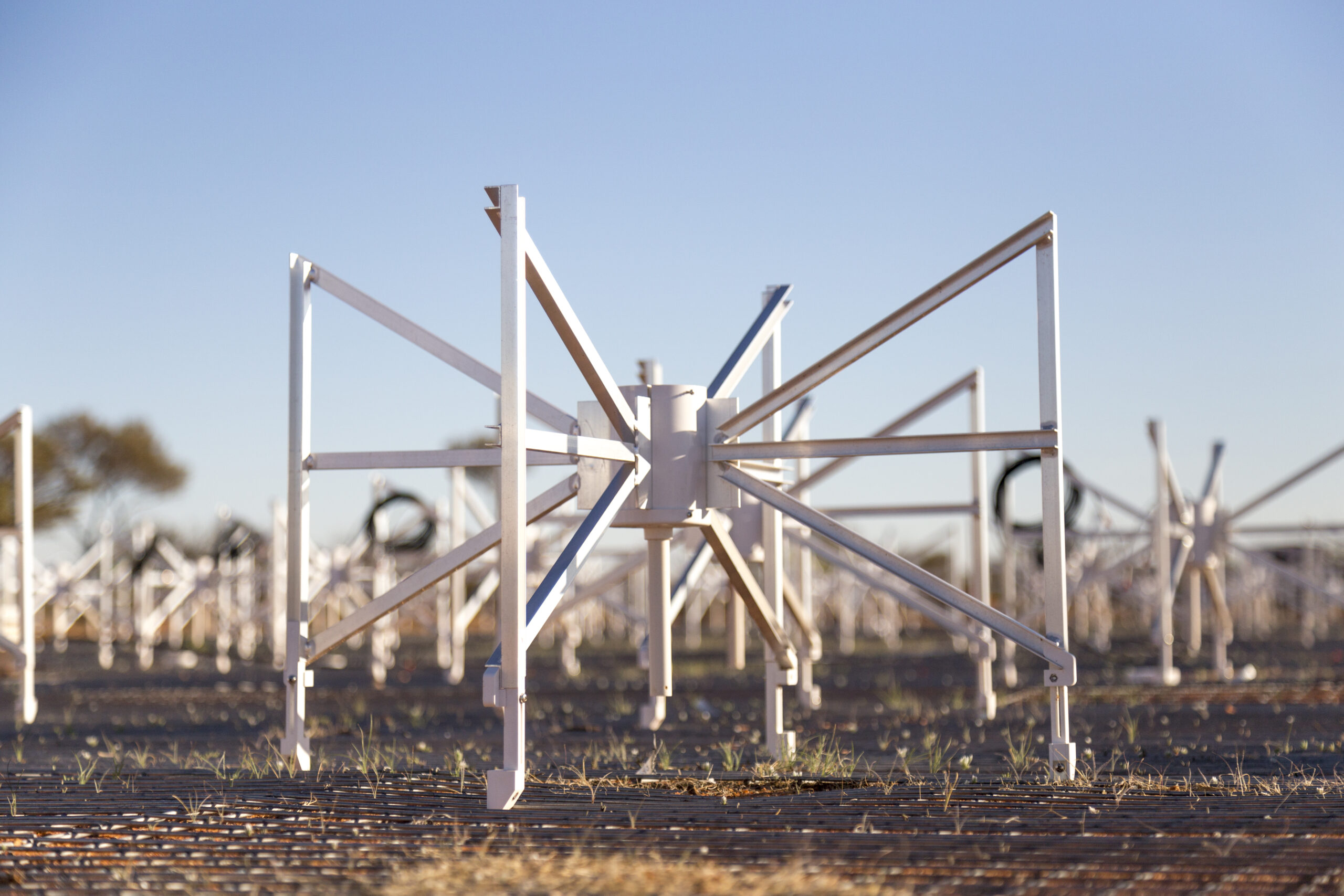
MWA antennas are a dipole design, made of aluminium, optimized for the 70-300 MHz frequency range. Each antenna is a pair of orthogonally crossed, vertical bowties (having dual-linear-polarisation), with a span of 74 cm and a height of 55 cm.
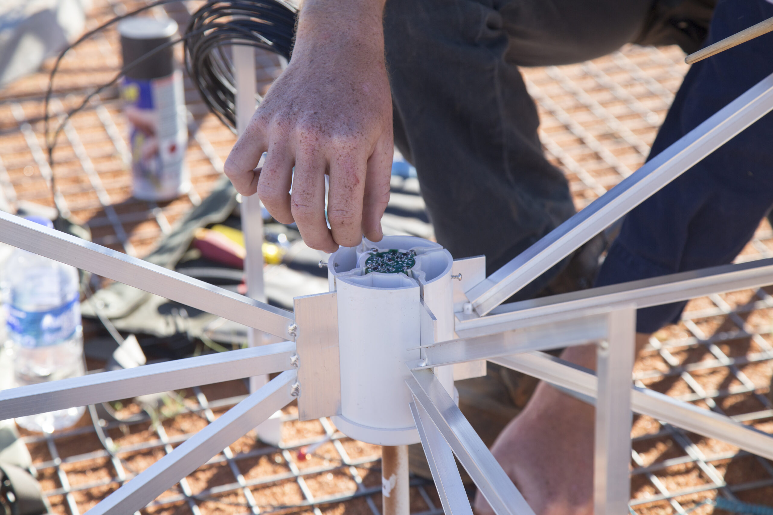
Each antenna is fitted with a low noise amplifier (LNA), placed between each pair of bowtie arms. The LNA amplifies incoming signals while adding less noise than is received from the coldest regions of our Galaxy.
The LNA for each element is housed in a protective, UV-resistant hub, to which the vertices of the bowtie arms are also attached.
Credit: ICRAR/CurtinCredit: ICRAR/Curtin
Tile
MWA antennas are arranged into ’tiles’. Each tile is a small phased array of 16 antennas in a planar, 4×4 square grid, with 1.10-meter spacing corresponding to half a wavelength at 136 MHz.
The antenna elements are are held ~10 cm above the ground screen by dielectric “feet” that clip to the ground screen mesh. The mesh, which has a 5×5-cm square grid pattern, is made of 3.15-mm-diameter galvanized wire. Three mesh panels, each measuring 2×5 meters, are overlapped slightly to form a 5×5-meter ground screen.
The mirror effect of the ground screen causes the pattern to roll off rapidly at elevations below 30°, with consequent enhanced rejection of terrestrial RF interference.
Credit: Marianne Annereau, 2015
Beamformer
The beamformer is a device (the small white box next to each tile) that allows the telescope to track objects in the sky.
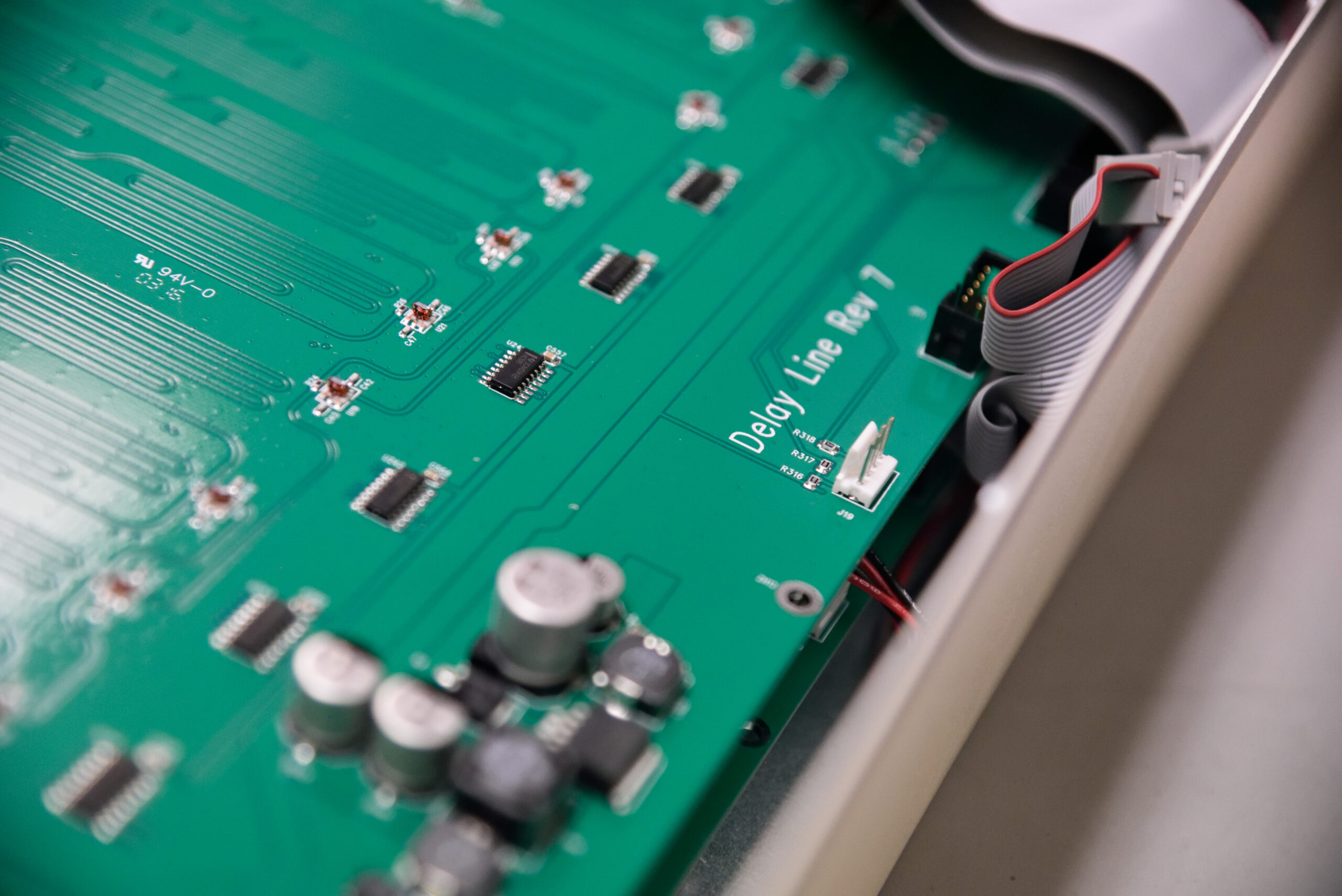
The beamformer receives signals from all 16 antennas in a tile, and applies independent delays to each signal in a manner appropriate to form a tile beam in a particular direction on the sky. True delay steering is employed, rather than phase steering, in order to point the beam properly over the full operating frequency range. The beam is 15-50° wide (FWHM), depending on frequency.
The delays are generated passively in coplanar waveguide transmission lines laid out on a printed circuit board inside the beamformer. Delay sections of different lengths can be switched in or out of each signal path as required to steer the tile beam in the desired direction. The delayed signals are combined and amplified by the beamformer, then sent over coaxial cable to the receiver.
Each beamformer contains circuit boards that steer the telescope, by antenna signal delays. Credit: ICRAR/Curtin
The animation below shows the beam pattern of an MWA antenna tile, which changes shape as a function of frequency. The beam pattern represents where the antenna tile is sensitive to receiving signals, and it can be electronically steered in almost any direction. In this way, we can point the telescope without any moving parts!
The MWA tile beam pattern as a function of frequency. Credit: Maria Kovaleva, Curtin University
Receiver
The signal data is filtered and digitised by the receiver before being sent to the correlator over fibre-optic cable.
Each receiver accepts the analog data streams from 8 MWA tiles over coaxial cable, and outputs digital data streams on optical fibre. To do this, it digitizes the input RF signal after appropriate signal conditioning, and passes the data through a coarse polyphase filter to obtain 1.28 MHz wide “coarse” channels. Astronomers can then select 24 of these coarse channels (within the total tile bandwidth of 70-300MHz) for transmission, giving the MWA a total instantaneous bandwidth of 30.72MHz.
The receiver enclosure is weather tight, and shielded against radio emissions.
Credit: ICRAR/Curtin
Solar power
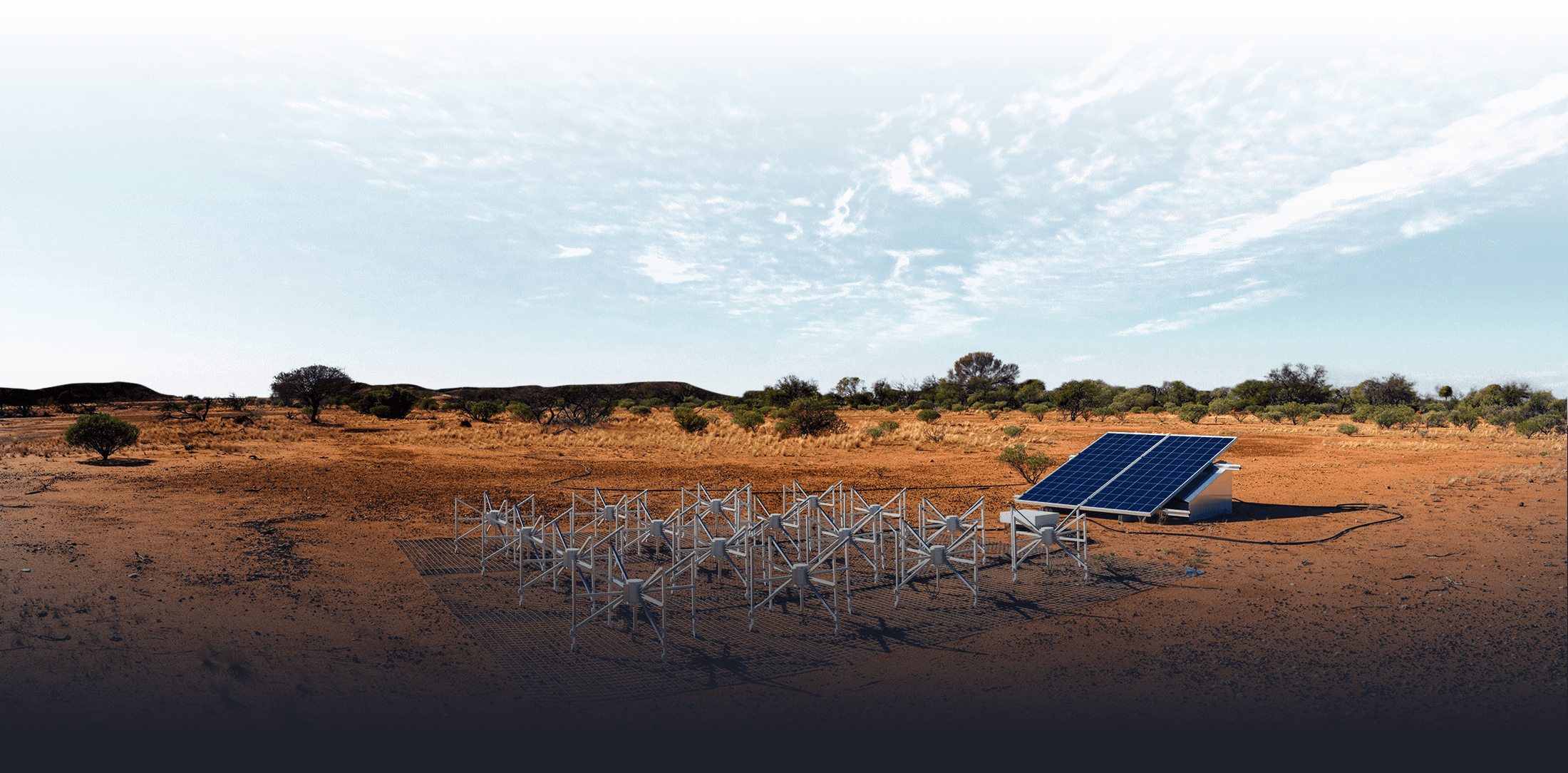
Some of the tiles in the MWA are located at distances in excess of 500m from any receiver. Usually the receiver would send power to the tile’s beamformer, but for these far-away tiles, solar power is far more effective. And instead of sending data back along coaxial cables (which would introduce losses and noise over those long distances), these tiles are connected to their receivers by optical fibre. These far-away tiles have a device called a Beamformer Interface, or BFIF, which manages the communications over the optical fibre link, and the solar panel power supply.
Credit: ICRAR/Curtin
Corner-turn
The data packets from the receivers need to be organised before being processed further. Currently this is achieved by a switch and a ‘media conversion’ server, shown in the animation below. After the MWA antenna signals are digitised by a receiver (turning the analog signals into 1’s and 0’s), the media conversion server helps to sort all this data by frequency. Different coarse channels are represented here as different colours. A switch then sends each coarse channel to a dedicated correlator server. This process is known as the corner-turn operation.
Correlator
The correlator is the ‘brain’ of the telescope; a huge bank of servers that perform the mathematical operations to correlate the information from all MWA antennas together at once. The correlator, called ‘MWAX’, is situated on-site at the Murchison in the CSIRO control building.
We’re pleased to announce the 2026 MWA Project Meeting will be held at Brown University in Rhode Island, USA. We invite you to join us from the 27th-30th July 2026 as we celebrate the theme Phase III and toward the EoR. Online attendance is encouraged. To find out more, visit the event website. Registrations are OPEN for […]
The 2026A Call for Proposals is now open for the Guaranteed Time and Open Access categories for the period commencing 4 May to 31 December 2026. Available Array Configurations and Re-Configurations In 2026A, proposers will be able to nominate a preferred array configuration from an initial set of options. The configurations offered have been formulated to optimise different performance figures of merit and to address […]
See our galaxy like never before. This stunning image of the Milky Way was captured using some of the longest wavelengths of radio light from the Murchison Widefield Array (MWA) in Western Australia. The image was created from combining the data of two major surveys of the sky — GLEAM (2013–2015) and GLEAM-X (2018–2020). Curtin […]
Author: ICRAR Astronomers from the International Centre of Radio Astronomy Research (ICRAR) have created the largest low-frequency radio colour image of the Milky Way ever assembled. This spectacular new image captures the Southern Hemisphere view of our Milky Way galaxy, revealing it across a wide range of radio wavelengths, or ‘colours’ of radio light. It […]
Lucien Wilkinson – Curtin University Western Australia’s Murchison Widefield Array (MWA) has entered its next chapter, with the completion of an upgrade set to expand our view of the Universe and solidify WA’s role as a global hub for radio astronomy. Operating since 2013, the MWA is a powerful telescope comprising 8,192 antennas spread across […]
We’re pleased to announce the 2025 MWA Project Meeting will be held in the stunning city of Perth, Australia. We invite you to join us from the 27th-29th August, 205 at the ARRC Building, Kensington, followed by a special Sundowner event to celebrate the official launch of MWA Phase 3. To find out more, visit […]
The 2025A Call for Proposals is now open for the Guaranteed Time and Open Access categories for the period commencing in June 2025, to the end of March 2026. Due to soon to-be-scheduled site-wide maintenance being conducted by CSIRO in late May or early June, the exact commencement date for the semester will be advised in […]
We would like to congratulate Associate Professor Natasha Hurley-Walker, from the Curtin University node of the International Centre for Radio Astronomy Research (ICRAR), for being awarded the prestigious 2025 Nancy Millis Medal for Women in Science by the Australian Academy of Science. Associate Professor Hurley-Walker’s research utilises powerful supercomputers to analyse petabytes of data from […]
Researchers from Curtin University, led by Associate Professor Natasha Hurley-Walker, may have uncovered how long-period radio transients were formed. The team discovered that M dwarfs (low-mass stars) in binary systems with another object, likely a white dwarf, produce powerful radio emissions as they interact with one another. The radio signal was detected in data from […]
This year’s MWA project meeting was held in Lausanne, Switzerland, from August 28th to 30th, hosted by the Swiss consortium through SCITAS-EPFL. The event brought together researchers, engineers, and experts from around the world, united in advancing radio astronomy and the MWA’s scientific objectives. The three-day meeting featured a range of presentations, discussions, and collaborative […]
Overview The Call for Proposals for MWA observing semester 2024B is now open. This is for the allocation of observing time in the Guaranteed Time and Open Access categories, nominally during the period October 28, 2024 to End-March 2025 (subject to availability of the array). The telescope will be in the extended configuration for the […]
We would like to congratulate our very own Professor Steven Tingay for winning the APM Professions Award category of the Western Australian of the Year Awards last night! The prestigious award-giving body recognises Steven’s outstanding contribution to the state, and his crucial role in securing half of the Square Kilometre Array (SKA) project for Western […]
This year, we’re thrilled to announce that our meeting will be hosted in Switzerland, marking the latest addition to the MWA Collaboration’s international network of collaborators. Radio astronomers are invited to join us from Wednesday, August 28th, to Friday, August 30th, 2024, at Swiss Federal Institute of Technology (EPFL) in the picturesque city of […]
CSIRO’s incoming CEO, Prof. Doug Hilton, together with the Shadow Minister for Science, Hon. Paul Fletcher, embarked on a notable tour of the MWA as an integral part of their visit to the Inyarrimanha Ilgari Bundara Murchison Radio Astronomy Observatory. The said visit not only marked a collaborative effort to foster a deeper appreciation for […]
2023 September 27 – The MWA Collaboration has been selected as a finalist for the 2023 Engagement Australia Excellence Awards, in the category ‘Excellence in International Engagement’!
The Murchison Widefield Array (MWA) project is celebrating a decade of operations this week. To mark the significant occasion, the global astronomy community has gathered in Perth for the milestone. 2023 July 26, Curtin University
Overview The Call for Proposals for MWA observing semester 2023B is now open. This is for the allocation of observing time in the Guaranteed Time and Open Access categories, nominally during the period September 29, 2023 to February 29, 2024 (subject to availability of the array). The telescope will be in the compact configuration for the duration […]
The technical description paper, “MWAX: A new correlator for the Murchison Widefield Array” by Morrison et al. has now been published in PASA. 2023 April 27
Finding the astronomical equivalent of a needle in a haystack, the ‘SMART’ way! A team led by ICRAR-Curtin researchers have published details in PASA of how they are using the MWA telescope to find new pulsars in our galaxy. 2023 April 27, Space Australia
Overview The MWA Semester 2023A Call for Proposals (CFP-2023-A) is now open, for observations during the period April 1, 2023 to August 15, 2023 (subject to availability of the array). 2023A Details This Call is for the allocation of telescope observing time in the Guaranteed Time and Open Access categories. The array will be in […]
Thirty years after the Square Kilometre Array radio telescope was proposed and a decade after WA was chosen to host the project, work is starting on the final stage of one of humanity’s greatest ever scientific endeavours. 2022 December 5, The West Australian
In 2022, Ernst and Young (EY) delivered an assessment of the Economic and Social Impact of the Murchison Widefield Array (MWA). The report examines the strategic, financial, and scientific dimensions of the MWA, and finds that the MWA has had a significant impact.
MWA researcher Dr Natasha Hurley-Walker and MWA operations team member Mia Walker won Shining Star awards at the annual Women in Technology WA Awards, 2022 November 18.
Pulsars create repeating flashes of radio light, and are so regular that you can set your watch to them. In fact, that’s exactly what some astronomers want to do! 2022 June 28, ICRAR
PhD candidate Kathryn Ross has co-won the 2022 WA science student of the year award! Ross’s research using the MWA telescope has helped shed light on our understanding of galaxy evolution. 2022 August 30, ICRAR
A team mapping radio waves in the Universe has discovered something unusual that releases a giant burst of energy three times an hour. 2022 January 27, Nature
The early Universe was dark, filled with a hot soup of opaque particles. These condensed to form neutral hydrogen which coalesced to form the first stars in what astronomers call the Epoch of Reionisation (EoR). 2021 November 29, ASTRO3D
A new $1 million Federal Government grant to Curtin University will enable a major upgrade to the Murchison Widefield Array (MWA). 2020 December 10, Curtin Media Release
Professor Steven Tingay (Curtin) was jointly named WA’s Scientist of the Year 2020, for his impactful research and early leadership of the MWA project. 2020 September 30, WA Government
Using the GLEAM surveym Dr Hurley-Walker and her colleagues discovered the remnants of 27 massive stars that exploded in supernovae at the end of their lives. 2019 November 20, ICRAR and ABC news
Researchers using the Murchison Widefield Array radio telescope have taken a new and significant step toward detecting a signal from the period in cosmic history when the first stars lit up the universe. 2019 November 26, Brown University
Astronomers are closing in on a signal that has been travelling across the Universe for 12 billion years, bringing them nearer to understanding the life and death of the very earliest stars. 2019 September 10, The Age, ASTRO3D, VICE, Phys.org,
What sounds like a stomach-turning ride at an amusement park might hold the key to unravelling the mysterious mechanism that causes beams of radio waves to shoot out from pulsars − super-magnetic rotating stars in our Galaxy. 2017 March 21, Curtin University Media Release
The recently launched Cisco Internet of Everything Innovation Centre at Curtin University is already generating dividends, with a successful trial last week of a 100Gb/s data link between the MWA and Curtin. 2016 March 16, Curtin
For the first time an international team of scientists, using a combination of radio and optical telescopes including the Murchison Widefield Array (MWA), has managed to identify the precise location of a fast radio burst (FRB). 2016 February 25, Curtin University Media Release
Curtin University’s work with the Murchison Widefield Array was recognised at the Thomson Reuters Citation and Innovation awards. 2015 June 14, PerthNow
A combination of pop songs, talkback radio and cutting-edge science has enabled Australian astronomers to identify a way to prevent catastrophic, multi-billion dollar space junk collisions, a new study has revealed. November 29, 2013, CAASTRO, Science Daily and CNet, December 02 by Voice of America
In the remote outback of Western Australia, astronomers are tuning in on the universe in the hope of unravelling the secrets of the cosmic dark ages. 2013 February, Qantas In The Air
A little-known fact is that Australia, a land blessed with low light pollution, has more than its fair share of great observatories. 2012 November 23, Australian Geographic
IBM computing cluster to help Australia’s Murchison Widefield Array process massive amounts of data captured from epoch when galaxies first formed. 2012 July 24, Cision
Boolardy station near Mullewa in Western Australia has been chosen as a candidate for the $2 billion Square Kilometre Array radio telescope project. 2011 May 15, ABC Landline